Updraft Wind Turbine:
background
Wind
power accounts for about 8
percent of the electricity produced in North
America. Some 50,000 + large wind turbines
crank out power throughout the continent.
These massive wind turbines, up to 100 meters
tall, capture energy in the wind and convert
it electricity that people can use to run
dishwashers, air conditioning and lights. That
8 percent may not sound like much until we
realize that the wind power is just catching
on. Huge new wind farms accounting for
thousands more megawatts of capacity are in
the development.
Trouble
in
the industry
Conventional
wind
turbines with large blades are destructive
to communities and local environments.
Animal habitats are disrupted and wildlife
is driven from the area. Noise and
vibrations cause human health problems. Home
values and real estate prices are reduced.
How does it work
In a conventional design,
large diameter blades, turbine-generator and
other heavy equipment are mounted on top of
the tower. Our design brings the small
diameter turbine-generator back to the ground
level, eliminating many shortcomings of the
conventional wind turbines. The only elevated
portion in our design is a balloon based
intake, which does not have moving parts.
Balloon allows the intake to be floated to
higher elevations. That flexibility does not
exist with a rigid tower.
The balloon lifted intake,
made of light materials, incorporates a
venturi system interconnected to the ground
based wind turbine by a lightweight pipe.
Wind, with a help of the venturi effect
induces air updraft to power the turbine
generator. In addition, a natural updraft
based on the buoyancy due to pressure and
temperature difference between the ground
level and the balloon helps to produce energy,
even in the absence of the wind.
To sum up, a balloon based WindUpdraft
system makes conversion of wind energy to
electrical power safer and more economical.
Background
of the invention (Canadian Patent 2,808,001)
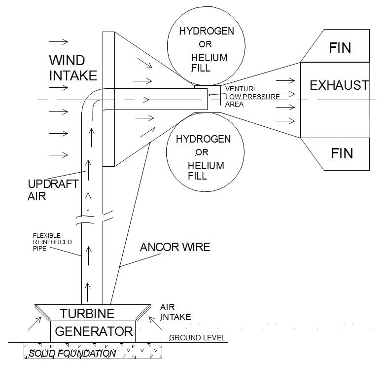
The purpose of the system is
to collect energy generated by airflow from
the wind, extract it and convert it to
electricity. A lighter than air helium filled
balloon is used to lift air intake portion of
a wind energy conversion system in order to
harness the wind energy. The turbine and the
generator are mounted on the ground. The
intake nozzle assembly is configured to
receive and to accelerate wind. The
accelerated wind creates low air pressure area
in the venturi piping downstream of the
balloon. This point of suction is where a
lightweight reinforced piping connects to
allow the air from the ground to be drawn in
the upward direction. The resulting air
movement spins the ground mounted turbine and
the generator. The mounting of the generating
system on the ground allows economical
maintenance due to relatively easy access.
MAIN COMPONENTS OF THE SYSTEM
The
system
shown on the drawings is the proprietary system
being registered in Canada for patent
protection, and comprises of the following main
components (Fig.1):
Base
Generator
Turbine
Flexible tube
Outer shell
Balloon
Venturi piping assembly
(Fig.2)
Helium filled balloon
The wind enters the outer shell of the wind
concentrator mounted on the helium balloon,
(Fig.1). It is shaped similarly as the intake of
a jet engine. Due to the laws of the physics the
wind speed will increase as the pipe diameter
decreases. The increased air speed creates area
of lower air pressure due to the venture effect.
This becomes our connection point to the
vertical pipe which leads to the turbine and the
generator mounted on the ground level. The lower
air pressure causes a high velocity air to flow
up in the pipe from ground intake to the
balloon. This high velocity air movement causes
the turbine to spin. A generator, connected to
the turbine converts the mechanical spinning
motion of the turbine into electricity.
A
high strength cable system extends from the
ground to the balloon to ensure the mechanical
integrity under the worst weather conditions.
The system turns always towards the wind with
the help of the stabilizer fins.
The initial operating altitude of the system will be approximately 10 to 20 meters, subject of the local bylaws. In rural areas the air collection system can be elevated to 100 meters or beyond.
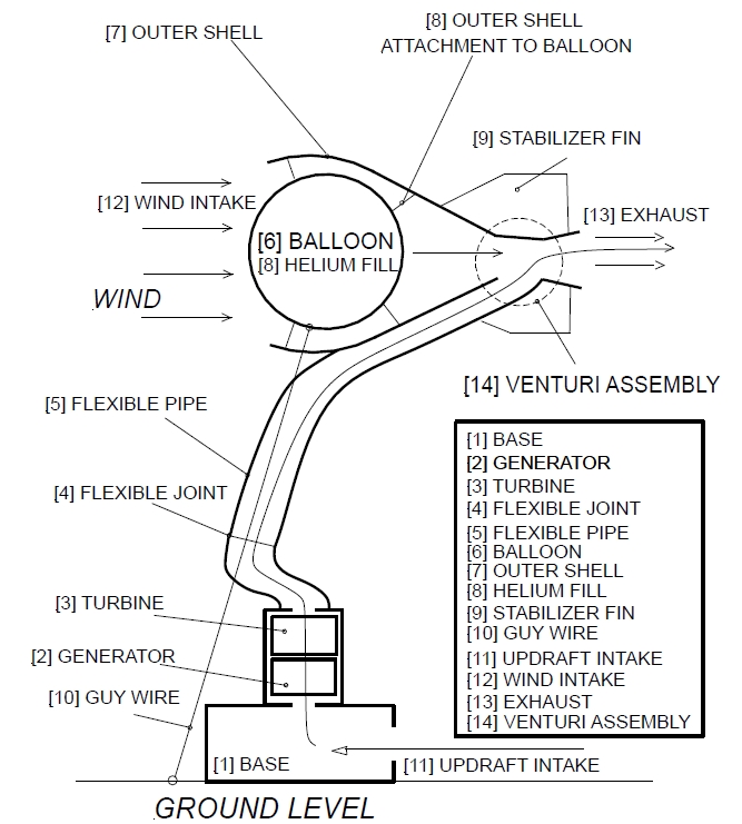
Fig. 1. WIND ENERGY CONVERSION SYSTEM Canadian Patent CA2808001
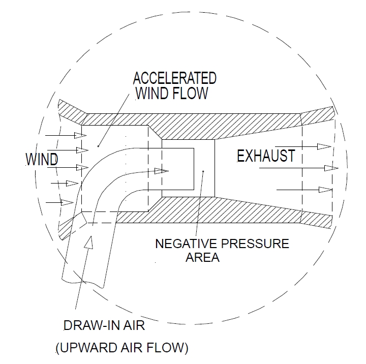
Fig.
2. VENTURI
ASSEMBLY – single stage shown for clarity
Additional Benefits: Heating and Cooling system
uWIN lands itself for a direct production of heating or cooling air, using vortex (Ranque-Hilsch) tubes. The updraft airflow in the pipe (Fig.3) passes through large vortex tube, where spinning air creates hot and cold air streams.
Conventional wind turbines
need to produce electricity first and then feed
electric power to heating or air cooling system.
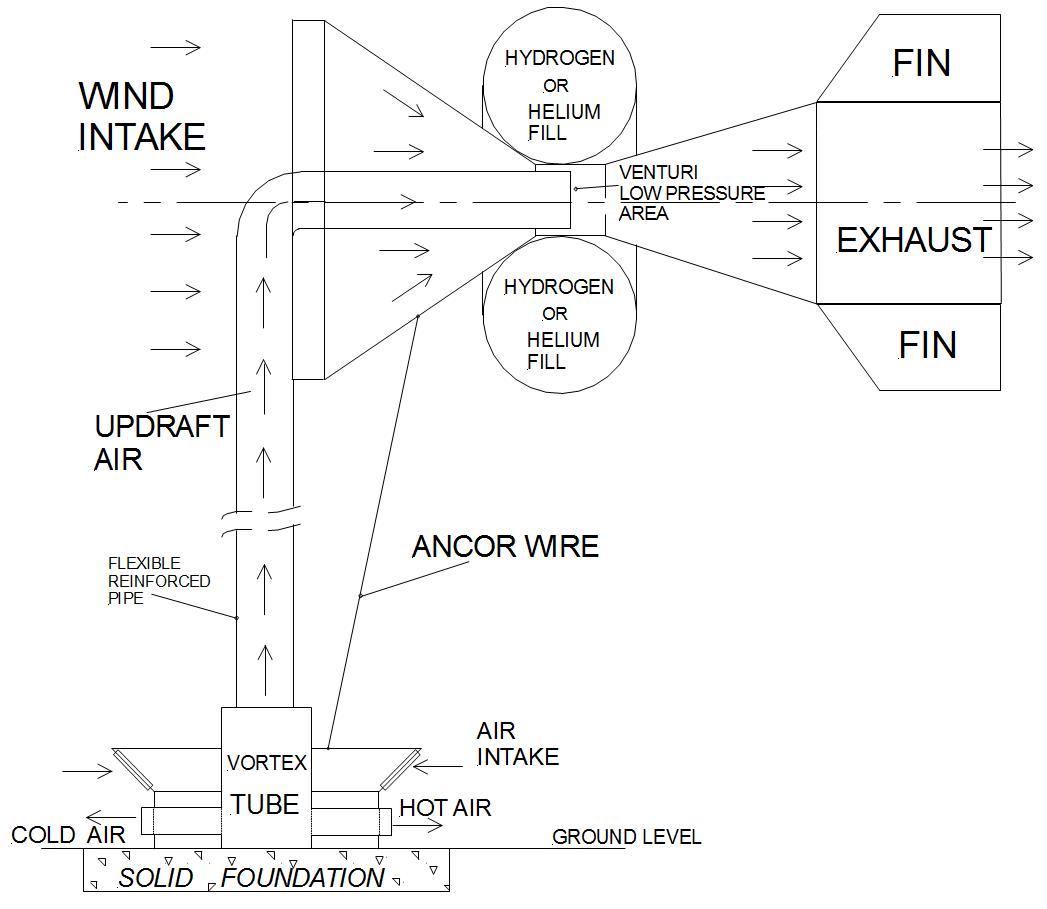
Fig. 3. VORTEX TUBE
APPLICATION FOR HEATING OR COOLING
Is this a
wildlife-friendly wind
turbine?
See attached article for
more details.